
In a multi-amplifier system, the ground path matters as much as the power feed. To understand how to properly ground a car amplifier, use a short ground wire that matches the power wire’s gauge and connect it securely to clean, bare metal. A poor connection can cause voltage drops, noise, or unreliable performance.
It’s easy to focus on the positive power cable and treat the ground as an afterthought. But every amplifier needs a dependable return path, and separate ground points can contribute to noise. In many installations, a shared ground reference and organized power-and-ground distribution help the system work together.
This guide explains what an amplifier ground does, how wire size and connection quality affect performance, and when a chassis connection or direct battery ground may make sense. You’ll also learn how to organize power and ground for several amplifiers and avoid wiring mistakes that can lead to noise, overheating, or shutdowns. The goal is a clean, reliable system, not just components that happen to turn on.
Key Takeaways
- Use a properly crimped ring terminal and a secure bolt or nut for a chassis ground; avoid self-tapping screws.
- Match the ground wire gauge to the amplifier’s power wire, and keep the ground path short to limit resistance.
- Route ground wiring away from sharp edges and heat, and pay attention to noise or shutdowns that can signal a connection problem.
- For multiple amplifiers, a central ground reference and organized power distribution can help reduce ground-loop noise.
How to Ground a Wire in a Car Stereo System Properly?
Knowing how to properly ground a car amplifier starts with choosing a dependable return path to battery negative. The main choice is whether current returns through the chassis or a dedicated cable.
Chassis Grounding Versus Battery Grounding
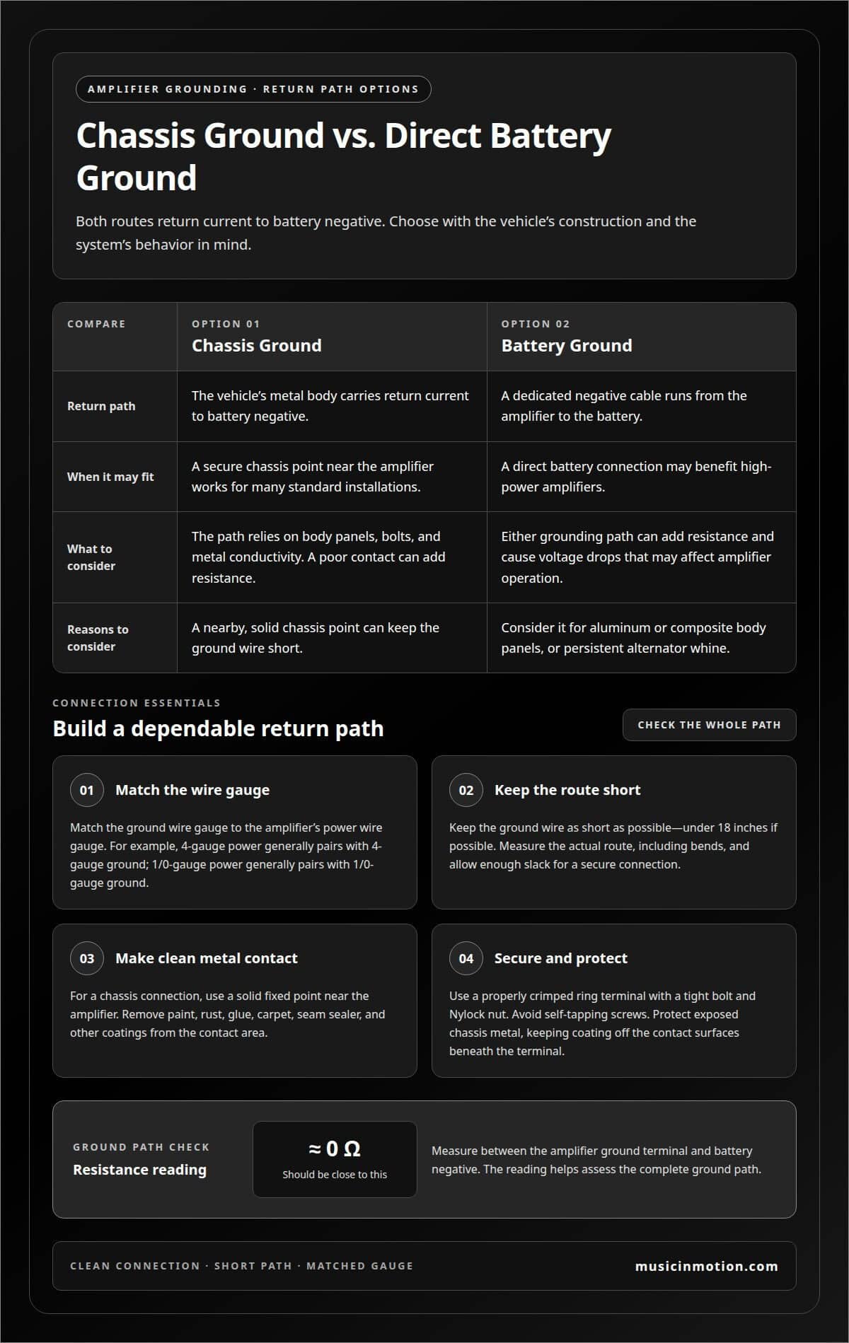
With chassis grounding, the vehicle’s metal body carries return current to battery negative. Battery grounding uses a dedicated negative cable from the amplifier to the battery. Either path can add resistance, causing voltage drops that may affect amplifier operation.
A secure chassis point near the amplifier works for many standard installations. High-power amplifiers may benefit from a direct battery connection, which avoids relying on body panels, bolts, and differences in metal conductivity. Battery grounding may also suit vehicles with aluminum or composite body panels. Persistent alternator whine is another reason to consider it. When learning how to properly ground a car amplifier, use the vehicle’s construction and the system’s behavior to guide your choice.
Selecting a Solid Chassis Ground Point
Choose a solid, fixed section of chassis near the amplifier to keep the ground wire short. The contact area must be free of paint, rust, glue, carpet, seam sealer, and other coatings. These layers prevent direct metal-to-metal contact and can weaken the connection.
Use a properly crimped ring terminal, secured tightly with a bolt and Nylock nut. Avoid self-tapping screws, which are not suitable for an amplifier chassis ground. A firm, flat connection keeps the return path stable. A loose connection can add resistance, cause voltage drops, and make amplifier performance unreliable.
Preparing a Bare-Metal Connection
Prepare the chosen chassis spot so the ring terminal touches bare metal directly. Remove paint, rust, glue, carpet, seam sealer, or other coatings from the contact area. A clean surface reduces barriers between the terminal and chassis, helping current return to battery negative.
After securing the connection, protect exposed chassis metal with a corrosion-resistant coating. Keep the coating off the contact surfaces beneath the ring terminal; metal must meet metal there. A ground-resistance measurement between the amplifier ground terminal and battery negative should be close to 0 ohms. That reading helps assess the complete ground path.
Should the Ground Wire Match the Power Wire?
Yes. Match the amplifier’s ground-wire gauge to its power-wire gauge, and keep the ground route short. Both choices help limit resistance in the circuit.
Matching Ground and Power Wire Gauge
The ground wire should match the gauge of the amplifier’s power feed. This prevents the return path from becoming the undersized side of the circuit. When planning how to properly ground a car amplifier, size both cables for that amplifier rather than choosing the ground wire separately.
For example, an amplifier using 4-gauge power wire should usually use 4-gauge ground wire. If the power feed is 1/0 gauge, the ground wire should usually also be 1/0 gauge. A smaller ground wire is a common wiring mistake because it can restrict the return path, even if the power cable is appropriately sized.
Considering Ground Wire Size and Length
Wire gauge and route length both affect resistance. Keep the ground wire as short as possible, and under 18 inches if possible. A nearby grounding point can help avoid an unnecessarily long cable run through the vehicle.
Measure the actual route from the amplifier’s ground terminal to its connection point, accounting for bends. A straight-line estimate may leave too little cable for a secure installation. Don’t add excess length or pull the wire tight. Aim for a compact route with enough slack for the connection and cable bends. This is essential to properly grounding a car amplifier without making the ground path longer than necessary.
Gauge alone doesn’t determine whether the circuit is well matched. A correctly sized wire routed far across the vehicle still creates a longer path than one connected nearby. Plan power and ground wiring together so the ground cable matches the power feed and takes a direct route. This provides a properly sized return path without unnecessary cable length.
Grounding safety and common mistakes
A poor ground connection can affect voltage and sound quality. Check cable routing, signal wiring, and changes in amplifier behavior.
Grounding Safety
Route the amplifier ground wire away from sharp edges and heat sources. Rubbing against a metal edge can wear through the insulation, while heat can damage the cable. Keep the insulation intact along the entire route, including where the wire passes through vehicle panels.
A weak ground can contribute to voltage drops, distortion, or amplifier shutdowns. In severe cases, a loose connection can heat the ground wire enough to melt it. If the audio system loses power intermittently or the amplifier shuts down, inspect the wiring path and connection instead of continuing to use the system unchanged.
Common Amplifier Grounding Mistakes
Don’t assume noise means the amplifier is defective before reviewing the installation. Poor wiring practices, signal-cable routing, and multiple grounding points can create unwanted noise. A ground loop may produce a whine that rises with engine RPM, linking the sound to vehicle operation.
Another mistake is routing power and signal cables together for long stretches. If their paths must cross, cross them at a 90° angle to help reduce electrical noise. Also avoid leaving a ground connection loose or routing its wire against a sharp edge. These faults can bring intermittent power loss, unwanted noise, or amplifier failure.
Use symptoms to guide a careful inspection. Alternator whine that changes with engine speed, for example, may point to a ground-loop or wiring issue, not necessarily a faulty audio component. Check whether signal and power cables run together and whether multiple ground points may be creating loops. Voltage drops can also reduce the voltage reaching the amplifier, leading to distortion or shutdowns. Address the wiring cause before changing signal settings or replacing equipment.
Power and ground distribution for multiple amplifiers
For multiple amplifiers, organize power and ground around a common reference. Test resistance between an amplifier’s ground terminal and battery negative; the reading should be close to 0 ohms. Amplifiers and other components can share a ground reference, helping reduce ground-loop issues.
Testing an Amplifier Ground with a Multimeter
A multimeter can measure resistance along the ground path and help identify a connection that may contribute to voltage drops. Set the meter to resistance and measure between the amplifier’s ground terminal and battery negative.
A reading close to 0 ohms indicates a low-resistance path. A higher reading points to resistance somewhere between those points, such as at a connection or along the vehicle’s ground path. This measurement evaluates the path as a whole, rather than proving every terminal is secure. Pair the result with a physical inspection of the wiring and connections.
Sharing a Ground Point
Sharing a ground point means connecting multiple system components to a common ground reference. In a multi-amplifier audio system, this can help reduce ground-loop issues caused by separate grounding points.
A centralized distribution layout brings power and ground connections to one location, then sends individual power feeds to source units, processors, and amplifiers. The shared reference gives those components a common electrical baseline. A poor ground or inconsistent connections can still create resistance and voltage drops, so keep distribution connections organized and secure.
Plan the distribution layout as one system, not as several unrelated amplifier installations. A common reference can reduce the chance of ground-loop noise, while separate ground points may create loops. The right arrangement depends on the components and their wiring paths. For example, a source unit, processor, and amplifiers can each receive individual feeds from a central location while sharing the system’s ground reference.
Planning a multi-amplifier layout? Arrange a custom audio installation for a coordinated power and ground design.
Music In Motion
Music In Motion turns car audio plans into complete installations, including systems with multiple amplifiers. A custom installation brings the power layout, ground connections, and component placement together as one system rather than treating each amplifier separately. This can help when you’re planning an upgrade, adding equipment, or addressing noise and unreliable performance in an existing setup.
With Car Audio Upgrades and Custom Installations, we focus on how the system is put together as well as the equipment it includes. If you’re weighing chassis against battery grounding or need a coordinated plan for several amplifiers, contact Music In Motion to discuss your car audio installation.
Plan Your Next Audio Upgrade With Confidence
A multi-amplifier system may change as you add components or adjust your listening goals. Before expanding it, consider how new equipment will fit the existing electrical layout, signal paths, and available installation space. Knowing how to properly ground a car amplifier gives you a useful foundation, but a coordinated design also accounts for how every component works together.
Music In Motion can help shape a car audio installation around your vehicle and the system you want to build. Share what you’re aiming to add or improve, and we can discuss an installation approach that brings the pieces together. Contact Music In Motion for installation help and take the next step toward a system designed for your drive.
Frequently Asked Questions
What Is an Amp Ground?
An amp ground is the electrical return path from the amplifier to battery negative. It completes the circuit, allowing current to flow through the amplifier and back to the vehicle’s electrical system. When an amplifier powers a subwoofer, for example, the ground path is as essential as the positive power feed. A poor return path can interfere with normal operation.
Can a Bad Ground Cause Alternator Whine?
Yes, a poor ground can contribute to alternator whine, often heard as a pitch that changes with engine speed. Multiple grounding points can also create a ground loop, introducing unwanted noise into the audio signal. If the whine changes with RPM, assess the ground layout and signal-wire routing together. Balanced or differential amplifier inputs can help isolate interconnect shields from chassis ground.
Can a Bad Ground Cause Voltage Drop?
Yes. Resistance at a poor ground connection can reduce the voltage reaching the amplifier, especially when the system demands more power. This may cause distortion or make the amplifier shut down during playback. If sound problems appear only during loud passages, assess the ground path along with the power feed.
Where should a car amplifier ground wire connect?
For a chassis ground, connect to solid, bare vehicle metal near the amplifier. The contact area should be free of paint, rust, and other coatings, with the ring terminal secured by a bolt and nut. A direct cable to battery negative may suit some high-power installations or vehicles with aluminum or composite body panels.
What gauge ground wire should I use for a car amplifier?
Use a ground wire with the same gauge as the amplifier’s power wire. The correct gauge therefore depends on the power cable selected for that amplifier. Don’t install a thinner ground wire just because the ground cable is shorter. A smaller-gauge return path can become a bottleneck, even when the positive feed is adequately sized.
How long should a car amplifier ground wire be?
Keep the ground wire as short as possible, and under 18 inches if possible. Measure the actual path from the amplifier terminal to the grounding point, including bends, rather than estimating a straight-line distance. Leave enough slack for a secure connection without pulling the cable tight. A longer route adds resistance, so a nearby suitable ground point can help keep the path compact.